

Today, most of the buildings have curtain walls. This increases the importance of using glass / composite materials. Calculation of the wind load on the façade by regulations varying between countries due to structure height, form and surrounding structures has been excluded from analytical calculations. The most widely used standard for Turkey “TS 498” not high structures (building height, which is made of less than 30.5m) with a fairly quick calculation is enough to get a solution. Internationally, the most widely used document in our region is “Eurocode EN 1991-1-4: Actions on structures, Part 1-4: Wind actions”. Every country maintains equivalent standards and regulations.
Alkazar’s practical calculation module for EN 1991-1-4, the Facade Wind Load Calculation Module, is part of UrClimate Tailor and is available to subscribers here:
Worked example: basic dynamic pressure
The first step of the analytical approach is the dynamic pressure formula: q = 0.5 × ρ × V². If we assume the wind velocity at a given height as V = 10 m/s and the density of air as ρ = 1.225 kg/m³ (standard air density at sea level):
| Step | Calculation | Result |
|---|---|---|
| Dynamic pressure | 0.5 × 1.225 × 10² | 61.25 N/m² (Pa) |
| kgf/m² equivalent | 61.25 / 9.80665 | ≈ 6.2 kgf/m² |
This is the reference dynamic pressure on the façade, before any zonal pressure coefficients are applied. In TS EN 1991-1-4, once the façade is divided into zones A–E, this reference value is multiplied by each zone’s own coefficient; in practice it is not the average value but the higher suction at corners and edges that governs. On a real project, V is derived from the site’s basic wind speed, terrain category and height-dependent corrections; the 10 m/s used here is simply an illustrative input to show the calculation step. Completing this process with purely analytical approaches requires knowing the varying wind speed for each region under many conditions, which is why our wind profile calculator and WindCalc module automate these steps.
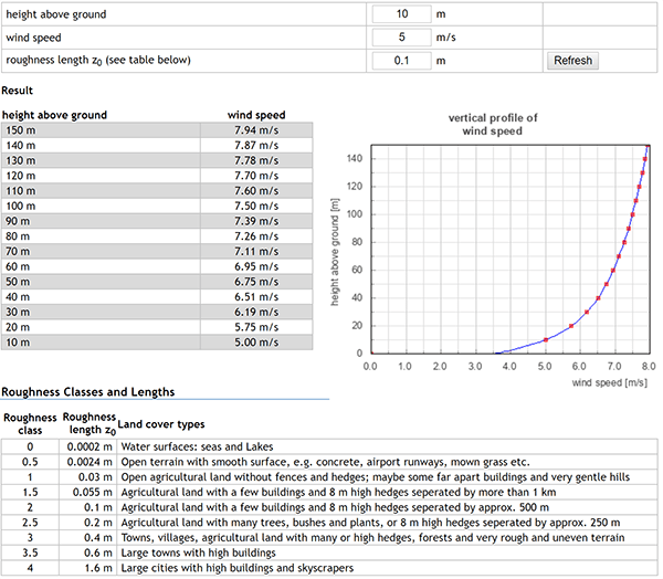
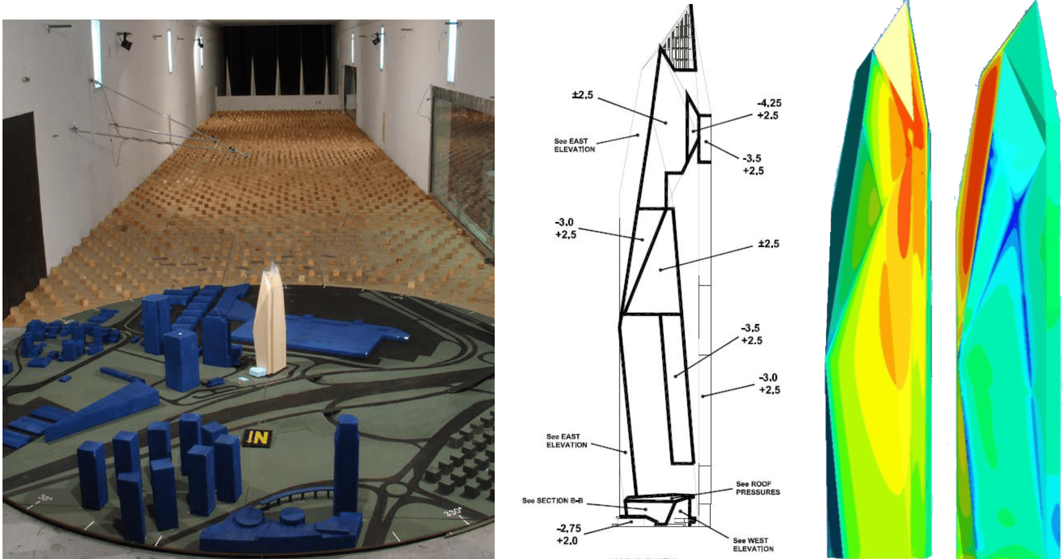
Critical situation in which the standards are not sufficient in calculating facade loads; It is problematic that the wind speed varies depending on the altitude and it cannot be predicted at what height the wind will blow due to the buildings and surrounding buildings where the calculations are made.
Therefore, the points to be considered in the analysis studies;
- Topography details,
- Surrounding structures,
- Surface roughness of the land.
Atmospheric Boundary Layer Wind Profile is defined to the boundary conditions by maintaining the entire flow volume. When the wind profile is created for analysis, the structure is exposed to wind load with angle changes of 10 with the automation developed by Alkazar. Thus, the load (positive) and suction (negative) load values that occur in 36 different directions in the facade surface are calculated. Subsequently, these loads are reported to the employer in 3D format and delivered to the building.
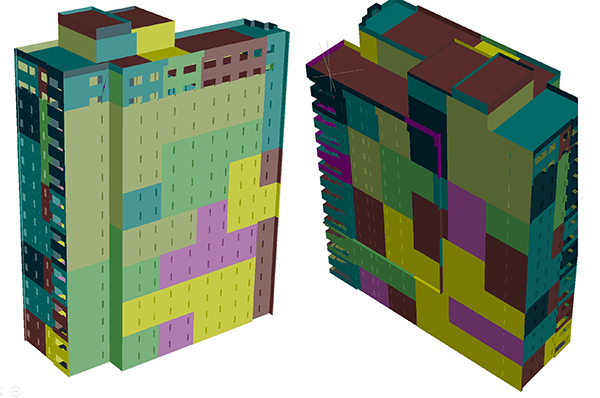
Thanks to computational calculation of wind load, it provides cost advantage by getting rid of the values that may be high tolerance value on the investor front. Or it can detect overloads at unpredictable points. The application firm or project managers will be presented in detail in which region the load will be critical. Thus, a report is prepared for the direct use of the facade consultants, the teams performing the calculations of the façade statics or the application side. In the delivered reports, a separate load value is calculated for each cladding zone and this detail cannot be used during the application. However, it is important to know all the risks in practice and make decisions accordingly. In this way, detailed reports increase the practice of our employers.
In determining the static loads that will affect the building core and defining the acceleration levels that will occur under wind load, we are at your side with a CFD set-up aligned with boundary-layer wind tunnel practice. Alkazar does not operate a physical wind tunnel; this is why it is important that the set-up provides the necessary and sufficient conditions for the atmospheric boundary layer.
TS 498 ↔ TS EN 1991-1-4 ↔ CFD comparison
| TS 498 | TS EN 1991-1-4 | CFD simulation (Alkazar) | |
|---|---|---|---|
| Scope | Fixed suction/pressure values by height; fast and simple | Detailed calculation with terrain category, turbulence, topography and zone coefficients | Numerical solution of the flow field for the actual geometry and surrounding context |
| Height limit | Fast solution for non-high-rise buildings under 30.5 m | Applies across the full height range, including tall buildings | No height limit; preferred for tall or irregular buildings |
| Surrounding effect | Does not cover neighbouring-building effects, funnelling or re-entrant corners | General rules; numerical analysis/wind tunnel recommended for complex surroundings | Sheltering/channelling from neighbouring buildings is modelled directly |
| Output | A single pressure/suction value varying with height | Zones A–E and coefficients depending on loaded area | Pressure coefficients and cladding-zone maps for every 10° of wind direction, plus 3D result files |
Process and deliverables
| Steps | Deliverables |
|---|---|
| Definition of the wind profile → CFD simulation (in 10° angle increments, 36 directions) → calculation of pressure/suction → cross-check against TS 498 / TS EN 1991-1-4 | Positive (pushing) and negative (suction) pressure values for 36 directions; cladding zone maps; 3D results in a single file (.dwg, .dxf, .3dm) |
Reference projects
- Luna Dragos (Maltepe, Istanbul): Façade wind-load calculations for a 3-block, 15-storey coastal residential project, accounting for venturi acceleration between blocks and the sloping topography of the Dragos ridge.
- Bomonti Hotel Project, Edesay (Şişli, Istanbul): Façade wind-load calculations for a 22-storey hotel façade in a dense urban fabric, addressing sheltering and corner-acceleration effects from neighbouring buildings.
- Raif Dinçkök Cultural Center (Yalova): Wind consultancy and outdoor comfort analyses for a cultural building with an approximately 5,600 m² perforated Cor-Ten steel shell.
- Anatolia Ceramic Production Facility (İzmir Aliağa): Determination of wind loads on the façade, alongside pedestrian-level wind comfort and daylight analyses, for a large ceramic production facility.
Facade wind loading: code calculation, CFD or wind tunnel?
Short answer: Alkazar calculates facade wind loads with CFD simulation, cross-checked against EN 1991-1-4 (Eurocode 1-4) and TS 498, for every 10° of wind direction. Deliverables are pressure coefficients, cladding zone maps and 3D result files. See also wind & CFD consultancy and pedestrian-level wind comfort.
Frequently asked questions
- What is facade wind loading analysis?
- It is the calculation of the peak positive (pushing) and negative (suction) pressures the wind applies to the building envelope, so that glass, panels, fixings and the supporting structure can be specified safely. Results are reported as pressure coefficients and cladding zones; corners, edges and parapets typically govern.
- When is CFD required instead of the Eurocode calculation?
- When the building is tall or irregular, when neighbouring buildings shield or channel the flow, when there are podiums, setbacks, canopies or double-skin facades, or when the code’s generic assumptions would be too conservative or unsafe for the actual geometry.
- Why can the Eurocode give higher loads than a simulation?
- Code values are envelope values, calibrated to cover a wide family of buildings and surroundings with a safety margin. A simulation reproduces the actual geometry and context, so local pressures often come out lower, and in some sheltered or channelled configurations, higher. We compare both.
- What is delivered?
- Pressure results for each wind direction (typically every 10°), cladding zone maps, peak and area-averaged coefficients, and 3D result files in the file formats the facade consultant or structural engineer requests.
- What determines the price of a facade wind loading study?
- It depends on the building’s height and geometry, the density of the surrounding urban context, the number of wind directions analysed, and the requested output formats; the final price is set according to project scope.
- Is CFD useful on a project where a wind tunnel report is required?
- Yes. Alkazar’s CFD set-up is aligned with boundary-layer wind tunnel practice: an atmospheric boundary layer inflow profile, modelling of the surrounding built context, and directional analysis in 10° increments; so results can be read alongside wind tunnel reports and code-based calculations. Alkazar does not operate a physical wind tunnel.
Related calculator: Alkazar WindCalc is an engineering module that calculates façade zones (A–E) and pressure coefficients for rectangular, L-, U- and T-shaped plans using the TS EN 1991-1-4 approach; it is available with an UrClimate Tailor subscription. For a quick pre-check, try our U-value calculation tool and wind profile calculator (Turkish-language tools). The calculation steps, the TS 498 height table and the codes used in Türkiye are explained in our wind load calculation guide.
