


Especially in tower projects, curtain wall design has become extremely critical in terms of cost, originality and attractiveness during the construction process. It stands in front of us as the most basic element that you can tell that your building is more extraordinary or qualified than the others when viewed from the outside, without living or visiting it. The building, which markets itself with its facade design, is extremely remarkable with its architectural predictions and its facade engineering calculations.

Although façade designs come to the fore with their differences in non-high-rise buildings, their main fatigue emerges in high-rise construction. One of the dynamics that high-rise construction brings to our lives is the change of wind velocities around the building. We know that wind velocities at ground level increase with increasing height of buildings. In addition, we can observe how it suppresses the microclimate while walking around or staying around, even during the day. There can also be serious differences between the strength of the wind blowing on the upper floors and the wind velocities blowing at the pedestrian level. As it is known, the wind profile definition is the logarithmic velocity value that changes depending on the height increase. In the upper floors, there are different dynamics brought about by these high-velocity wind movements in terms of structure, such as wind loads.
With the atmospheric boundary layer theorem, wind load or facade load calculations can even be analyzed analytically. This pressure created by the air (wind) is proportional to the square of its density and velocity. With a very simple approach, let’s assume that the wind velocity is 25 m/s for 10 m height. If we take the density of the air as 1.25 kg/m3, we calculate that the pressure on the surface is approximately 390 N/m² (about 40 kgf/m²). These assumptions can be very useful in determining the facade loads of non-high-rise buildings with simple facade types. In parallel with this, the wind load table below gives the suction pressure to be taken according to the height of the building.

The wind load calculations we consider come to the fore with the change of the form of the buildings, surrounding buildings, topography detail and height. For example, there are other tall buildings around your building. The wind that comes into contact with these buildings may be coming to your structure higher than the free-flowing wind velocity. In some cases, the wind that will come to you can reach your structure at a lower velocity with the barrier formed by other structures. In this case, you need to define a design criterion for the load value that will occur on the facade.
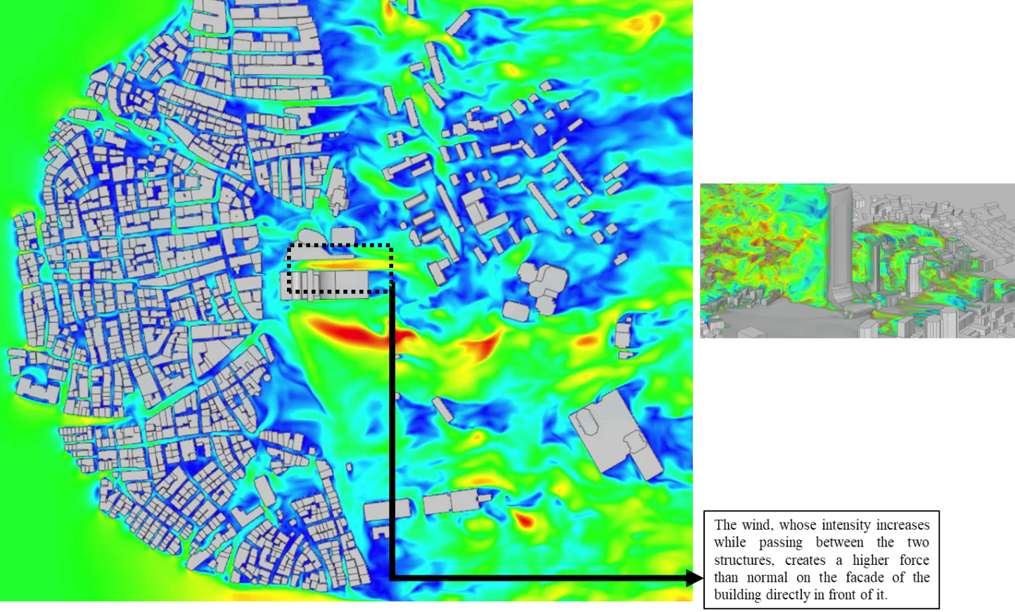
However, we know that wind accelerations may occur due to the form of your building. Let’s focus on a design that includes two tower buildings and serves as a shopping center in the lower usage base areas. The winds that are separated by hitting the towers cause the wind force in the lower floors to hit the facade faster due to the narrowing of the cross-section between the buildings. In the literature, we give the name of compression load (positive pressure) to the forces coming directly against the facade, while we call the forces at the point where the rapid wind is tangent to the surface of the flow separating the suction load (negative pressure). In our following articles, we will talk about exactly how we calculate these values numerically, how to prepare an easily interpreted report of wind load values.
Wind load table: wind speed and suction by height in the Turkish standard TS 498
The Turkish loading standard TS 498 (September 2021 edition, replacing the 1997 edition) covers wind in Clause 14. Suction is the velocity pressure: with an air density of 1.25 kg/m³ and the speed in m/s, q = v²/1600 kN/m². The height-dependent chart (Table 4 in the 2021 edition) gives:
| Height above ground (m) | Wind speed v (m/s) | Suction q (kN/m²) |
|---|---|---|
| 0 – 8 | 28 | 0.5 |
| 9 – 20 | 36 | 0.8 |
| 21 – 100 | 42 | 1.1 |
| > 100 | 46 | 1.3 |
The load on a surface is W = C · q, with C = 1.2 for surfaces normal to the wind in general and C = 1.6 for tower-type buildings whose facade height is at least five times the average width (Table 5); for a 30 m building the 21 – 100 m band gives q = 1.1 kN/m², so W = 1.32 kN/m² in general and 1.76 kN/m² for a tower-type building. For individual load-bearing elements such as rafters, purlins and facade elements the pressure coefficient is increased by one quarter (Clause 14.2.3). The standard notes that local topography can shift speeds away from the table, requires q = 1.1 kN/m² for buildings high on a steep slope, excludes bridges, cranes, tall chimneys, broadcast towers and overhead power lines, and refers to TS EN 1991-1-4 for building and roof types it does not cover.
EN 1991-1-4 (Eurocode 1) step by step
TS EN 1991-1-4 (the Turkish adoption of Eurocode 1, Part 1-4; Turkish Standards Institution, December 2007) derives the wind load from location, terrain and height instead of a single table:
- Fundamental basic wind velocity vb,0: the 10-minute mean at 10 m in terrain category II with an annual probability of exceedance of 0.02; the value is left to the National Annex. For steel buildings the Turkish steel structures regulation (Section 5.3 of the annex) sets minimums of 28 m/s for vb,0 and 0.5 kN/m² for the characteristic wind load.
- Basic wind velocity:
vb = cdir · cseason · vb,0(Expression 4.1), recommended factors 1.0. - Terrain and mean velocity: z0 and zmin from Table 4.1 (categories 0 to IV: z0 = 0.003, 0.01, 0.05, 0.3 and 1.0 m; zmin = 1, 1, 2, 5 and 10 m);
cr(z) = kr · ln(z/z0),kr = 0.19 · (z0/0.05)0.07,vm(z) = cr(z) · co(z) · vb(Expressions 4.3 to 4.5). - Turbulence intensity:
Iv(z) = kl / (co(z) · ln(z/z0))(4.7), recommended kl = 1.0. - Peak velocity pressure:
qp(z) = [1 + 7 · Iv(z)] · ½ · ρ · vm²(z) = ce(z) · qb,qb = ½ · ρ · vb², recommended ρ = 1.25 kg/m³ (4.8 to 4.10). - Pressure coefficients: vertical walls of rectangular buildings are divided into zones A to E using
e = min(b; 2h)(Clause 7.2.2, Figure 7.5); cpe,1 or cpe,10 from Table 7.1 depending on the loaded area; internal pressure cpi from the opening ratio, with +0.2 and -0.3 recommended when it is unknown (Clause 7.2.9). - Surface pressures and force:
we = qp(ze) · cpe,wi = qp(zi) · cpi(5.1, 5.2), the net pressure being their signed difference;Fw = cscd · cf · qp(ze) · Aref(5.3) with the structural factor from Section 6.
Worked numbers (industrial building example in the Turkish Ministry of Environment and Urbanisation’s steel design guide): z = 9.2 m, terrain category II and vb,0 = 28 m/s give cr(z) = 0.99, vm(z) = 27.72 m/s, qb = 490 N/m² and qp(z) = 1.12 kN/m² (ce(z) = 2.283); with cpe,10 = +0.8 on the windward zone D the external pressure is 0.90 kN/m², and with -1.2 in corner zone A the suction is 1.34 kN/m². The TS 498 table gives q = 0.8 kN/m² at the same height, but the two quantities are defined differently (velocity pressure versus peak pressure including turbulence), so any comparison should be made at the level of the final zone load. Why the two approaches diverge for the same building is discussed in our analytical versus numerical facade load comparison.
Facade loads, the codes used in Türkiye and calculation tools
Cladding is sized for local pressures on small areas, which is why EN 1991-1-4 interpolates between cpe,1 and cpe,10 for loaded areas between 1 m² and 10 m² and gives the highest suction in the corner and edge zones; TS 498 raises the coefficient for individual elements by one quarter for the same reason. Neighbouring buildings, re-entrant corners and podium massing fall outside the code envelope; there the facade pressures are resolved per wind direction with CFD and cross-checked against the code values, as described on our facade wind loading page and in the studies on how well EN 1991-1-4 represents neighbouring buildings and on 45-degree versus parallel neighbour layouts.
Four documents govern wind loads in Türkiye: TS 498 (Turkish Standards Institution, September 2021) for the height table and C coefficients; TS EN 1991-1-4 (Turkish Standards Institution, December 2007) for terrain, turbulence, peak pressure and zone coefficients; the steel structures regulation (Official Gazette, 4 February 2016, no. 29614, Section 5.3 of the annex) with its 28 m/s and 0.5 kN/m² minimums; and, for tall buildings in Istanbul, the Istanbul Tall Buildings Wind Code prepared for the Metropolitan Municipality by Boğaziçi University’s Kandilli Observatory (Version V, August 2009), which sets a basic wind speed of 25 m/s for Istanbul and requires wind tunnel testing for non-standard tall buildings and approval of tall building designs by an independent control board; whether the local authority applies it should be confirmed for each project.
The steps above map directly onto a spreadsheet (one row per height; columns for z0, cr, vm, Iv, qp, zone coefficient and we). Our free wind profile calculator plots wind speed and dynamic pressure against height for a chosen roughness class, and Alkazar WindCalc computes facade zones and pressure coefficients for rectangular, L-, U- and T-shaped plans (UrClimate Tailor subscription, Turkish-language interface). More tools are listed on the tools page.
References
- TS 498:2021, Yapı elemanlarının boyutlandırılmasında alınacak yüklerin hesap değerleri (Turkish Standards Institution, September 2021), Clause 14
- Çelik Yapıların Tasarım, Hesap ve Yapım Esaslarına Dair Yönetmelik (Official Gazette, 4 February 2016, no. 29614), Section 5.3 of the annex
- İstanbul Yüksek Binalar Rüzgâr Yönetmeliği, Version V (Boğaziçi University, Kandilli Observatory and Earthquake Research Institute, for the Istanbul Metropolitan Municipality, August 2009) (PDF, Turkish)
- EN 1991-1-4, Eurocode 1: Actions on structures – Part 1-4: General actions – Wind actions (CEN)
Related article: Rooftop solar panel: Position and orientation change the wind effect together