When calculating wind loads in dense urban environments, the dimensions of the main building are not the only factor. Nearby structures can also change the wind field, and this change is directly reflected in the pressure distribution on façades and roofs. This is why the key question is often: how well does EN 1991-1-4 represent the effect of neighboring buildings?
To answer this properly, we first need to clarify what the standard is designed to do. EN 1991-1-4 is not an aerodynamic model intended to resolve the flow around a building in detail. Its purpose is to provide a practical, code-compliant design approach while still accounting for the influence of the surrounding environment. In other words, the standard acknowledges the effect of neighboring structures, but it represents this effect through simplified engineering parameters rather than by resolving the flow field in detail, as CFD does.
What the Code Does, and What It Doesn’t
EN 1991-1-4 clearly recognizes that nearby structures can alter the wind field. Speed-up effects caused by taller neighboring buildings, as well as the general influence of closely spaced structures, are taken into account through simplified environmental assumptions. However, the limits of this representation are also clear. The standard does not determine exactly where the flow accelerates between two buildings, along which edge separation becomes stronger, how the wake region reorganizes, or on which surfaces local suction peaks become concentrated.
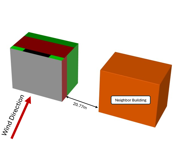
This distinction becomes even more apparent when considering a parallel neighboring building. In this type of arrangement, the actual flow accelerates through the gap between the two buildings and may amplify local effects on certain surfaces. EN 1991-1-4 does not treat this behavior as a detailed, direction-sensitive flow problem. In practice, it represents the effect more in terms of general speed-up, shielding, or the average influence of nearby development. As a result, the calculation output is not a distribution map showing the local flow mechanism. Instead, it provides design pressures defined for standard façade and roof zones.
For this reason, the code should not be interpreted as a flow solver. What EN 1991-1-4 does is reduce the effect of neighboring buildings to a level that can be used in design. This provides a strong framework, especially for early-stage design and code-compliant load definition. However, it does not aim to explain in detail how a neighboring building locally reorganizes the flow.
How Was the EN 1991-1-4 Calculation Prepared?
The inputs shown in the figure in this article were generated using our free EN 1991-1-4 calculation tool, Alkazar WindCalc.
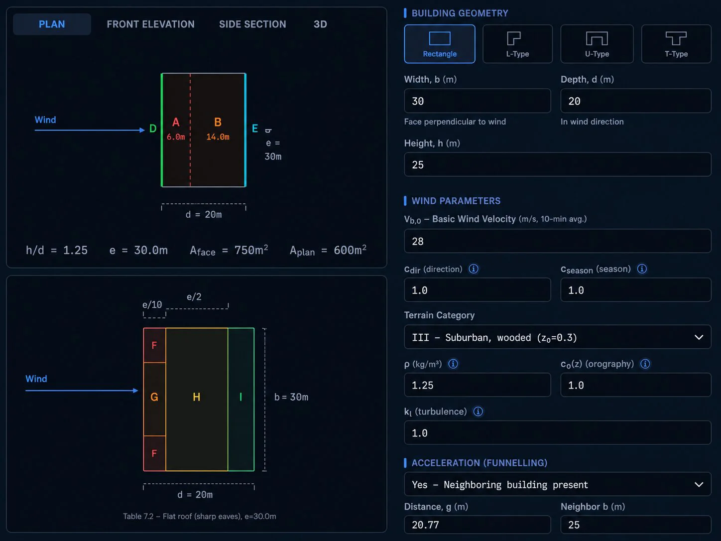
For the setup, the benchmark geometry was kept simple. The main structure was defined as a rectangular block with a width of 30 m, a depth of 20 m, and a height of 25 m. The reference wind speed was taken as 28 m/s at a height of 10 m. Terrain category III, with z0 = 0.3, was used. The neighboring building effect was included in the model through the presence of the adjacent building and its spacing relationship within the same general setup. In this way, the neighboring building effect was evaluated within the simplified calculation framework permitted by EN 1991-1-4.
For this reason, the EN 1991-1-4 figure represents a standardized design output rather than a resolved flow field. Wall and roof zones are shown separately, and the relevant external pressure coefficients and net design pressures are obtained through these zones. This is also where the neighboring building effect enters the system. The effect is present, but it is represented at a simplified, zone-based level.
Why Is the Parallel Neighboring Building Scenario a Good Example?
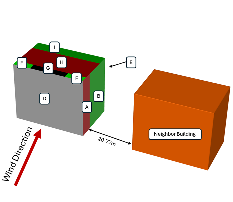
A parallel neighboring building arrangement is a useful example for explaining how EN 1991-1-4 represents neighboring building effects. In this case, the interaction between the two structures becomes easier to observe. The flow is squeezed through the gap between the two building masses and accelerates. This effect can become more pronounced around edges, corners, and roof regions. From a flow perspective, this is not only a general speed-up effect. It is a pressure field that redistributes across the surface.
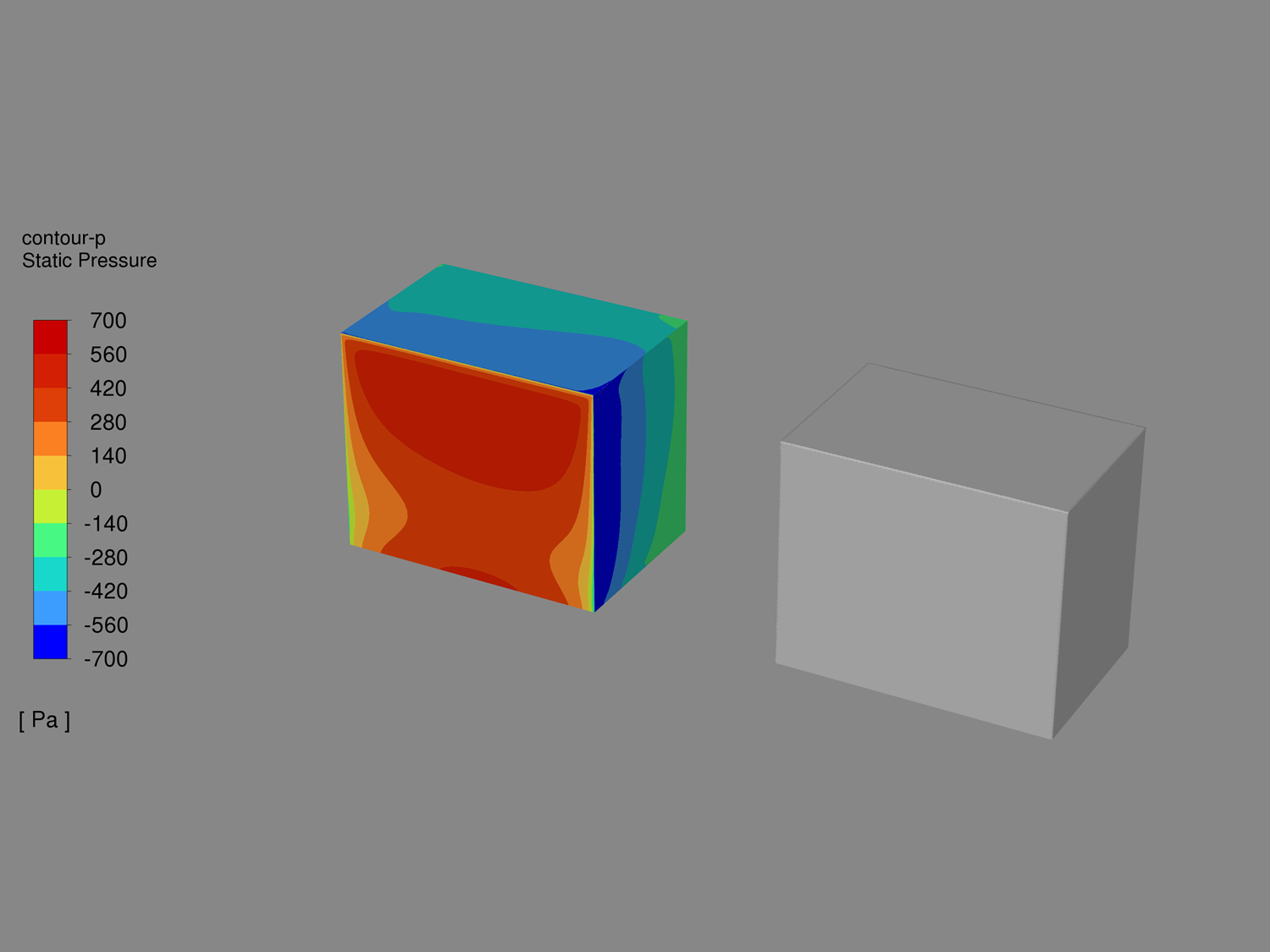
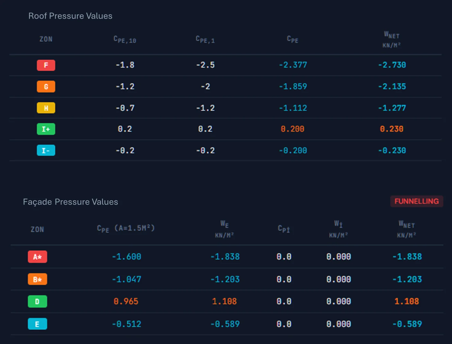
This distinction becomes clearer when the CFD contour image for the parallel neighboring building is examined alongside the EN 1991-1-4 output. On the CFD side, pressure is distributed as a continuous field over the building surface. The analysis shows that local accelerations developed due to the narrowed flow path between the two buildings, with stronger suction zones observed especially along the side edge, the roof, and the surface facing the neighboring building. Meanwhile, the presence of the neighboring building made this distribution more asymmetric across the surface. In other words, CFD interprets the neighboring building effect not as a single correction, but as a reorganization of the flow across the entire surface.
On the EN 1991-1-4 side, the same problem is handled at a different resolution. The result is not presented as a continuous contour over the surface, but as design pressures defined for standard zones such as A, B, D, E, or F, G, and H. This difference is not only a matter of presentation. It also shows the level at which each approach represents the problem. One makes the flow field and surface pressure distribution visible. The other converts the same physical situation into a code-compliant, zone-based design load.
The Main Engineering Takeaway
The main takeaway is this: EN 1991-1-4 does not completely ignore the effect of neighboring buildings. However, it also does not resolve this effect as a detailed aerodynamic interaction governed by the orientation of the neighboring structure and the local flow pattern. Instead, it provides a practical and generally conservative design framework based on changes in the overall wind field. In this example, the EN 1991-1-4 calculation does not describe the local distribution seen in the CFD contour one to one. Rather, it produces a broader, conservative design envelope. This makes it a strong starting point for preliminary sizing, code-compliant initial design, and the definition of standard façade loads.
In cases such as parallel neighboring buildings, where the interaction between two structures becomes stronger, the engineering question is not only the magnitude of the design pressure. It also becomes important to understand how this pressure is redistributed across façade and roof surfaces. At that point, the issue is no longer limited to a general speed-up effect. The local flow pattern, separation regions, and suction concentrations become important design factors. This is exactly where the boundary between code-based assessment and detailed flow analysis becomes visible.
Conclusion
So, to return to the original question: how well does EN 1991-1-4 represent the effect of neighboring buildings?
The answer is that the code represents this effect at a simplified, practical, and generally conservative level for design. It can account for the presence of a nearby structure as a general change in the wind field. However, it does not explain in detail how the neighboring building reorganizes the flow depending on its orientation, what local effects form in the gap between two buildings, or where these effects become concentrated on façade and roof surfaces. In other words, it takes the neighboring building into account, but it does not resolve the flow physics created by that building. Instead, it provides a code-compliant design load approach that remains conservative in most cases.
Related service: Facade Wind Loading (CFD & Eurocode) · Guide: wind load calculation, table and codes
Related calculator: try our facade wind load calculation module, WindCalc (Turkish-language).