Imagine a building, and you want to calculate the wind-induced facade loads. For this, you have 3 options,
- Wind Tunnel Testing (Experimental)
- Calculation according to Eurocode EN 1991-1-4 Standards (Analytical)
- Computational Fluid Dynamics Analyses – CFD (Numerical)
Although wind tunnel tests are not often preferred due to their high cost, analytical or numerical calculation methods can be used instead. That is exactly what was done in this article. The same building geometry was first calculated with Alkazar’s Wind Calculator, calibrated according to Eurocode EN 1991-1-4 standards, and then calculated again through CFD analyses based on its 3D model.
- A roof with a 15° angle in the direction facing the wind was also added to a building with a height of 50 meters, a width of 30 meters, and a depth of 20 meters.
- A wind profile of 28 m/s was defined at the 10 m reference height. (This is a wind speed assumption that varies by location and has an annual probability of exceedance of 0.02 at a 10-minute average.)
- Terrain Category III was selected and z0 = 0.3 was taken.
- With the ground roughness value input, the wind speed also increases as the height increases.
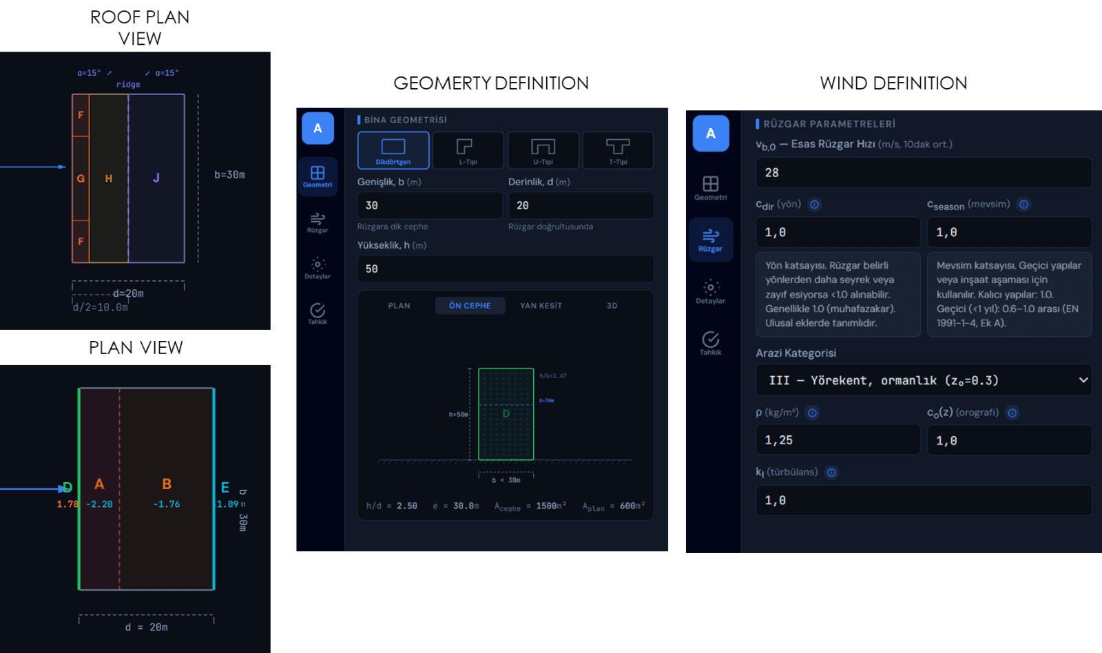
Wind calculator interface
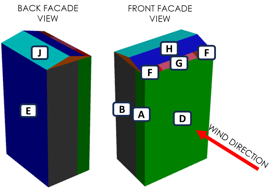
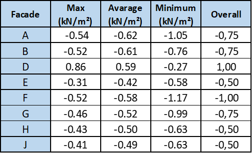
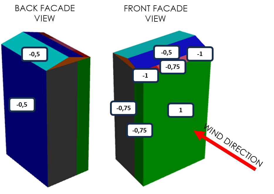
Letter codes of the building facade surfaces according to Eurocode standards

The results are displayed in this way in the Calculator. Since we do not have I+, I− and C surfaces, the most refined state is shown directly on the facade. The loads are plotted on the visual in kN/m² (kPa).
Eurocode does not “solve the flow”; it produces a design output on the safe side
The aim of EN 1991-1-4 is not to resolve every vortex of flow physics, but to provide the characteristic wind action to be used in design. The standard addresses loads through the “loaded area” approach; in other words, it focuses on producing results on the safe side for the entire structure, structural parts, cladding elements, and connections.
The fundamental wind velocity is not just an ordinary daily wind; it is defined at a height of 10 m, in open terrain, as a 10-minute average with an annual probability of exceedance of 0.02. In addition, cpe,1 is used for small elements and cpe,10 for large areas; in other words, a more conservative framework is introduced that also includes local peaks in elements such as glass, cladding, and anchors. Moreover, the coefficients given for orthogonal directions represent the most unfavorable values within the ±45° range on either side of the relevant direction.
It cannot take detailed building geometry into account; it can be used for simple rectangular buildings, canopy structures, and L-shaped and T-shaped building plans.
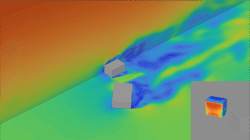
This is where CFD’s strength begins: the same conditions, more physics
- In CFD, the flow is actually solved.
- Since we defined the same 28 m/s reference wind, the same profile logic, and the Atmospheric Boundary Layer (ABL), the difference that arises here comes not from the input difference, but from the method difference.
- CFD can capture time-dependent fluctuations on the facade, corner separations, recirculation, the contribution of surrounding buildings, and even, if desired, the effects of glass panels, parapets, sunshades, and projections.
- It offers the possibility to resolve all recesses and protrusions of the building, the window and louver surfaces that are very critical for the calculation, and the entire custom-designed geometry.
- Eurocode does not completely ignore the effect of surrounding structures; however, it still handles this through limited and conservative rules. CFD, on the other hand, says, “bring whatever exists around into the model.” This is also why the LES approach is powerful; because it makes it possible to track large time-dependent turbulent structures and transient behavior.
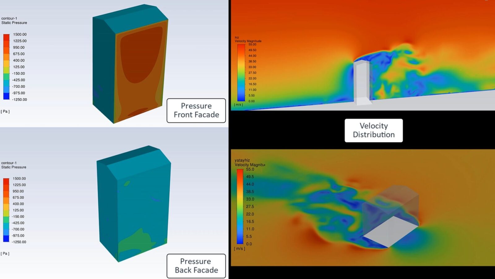
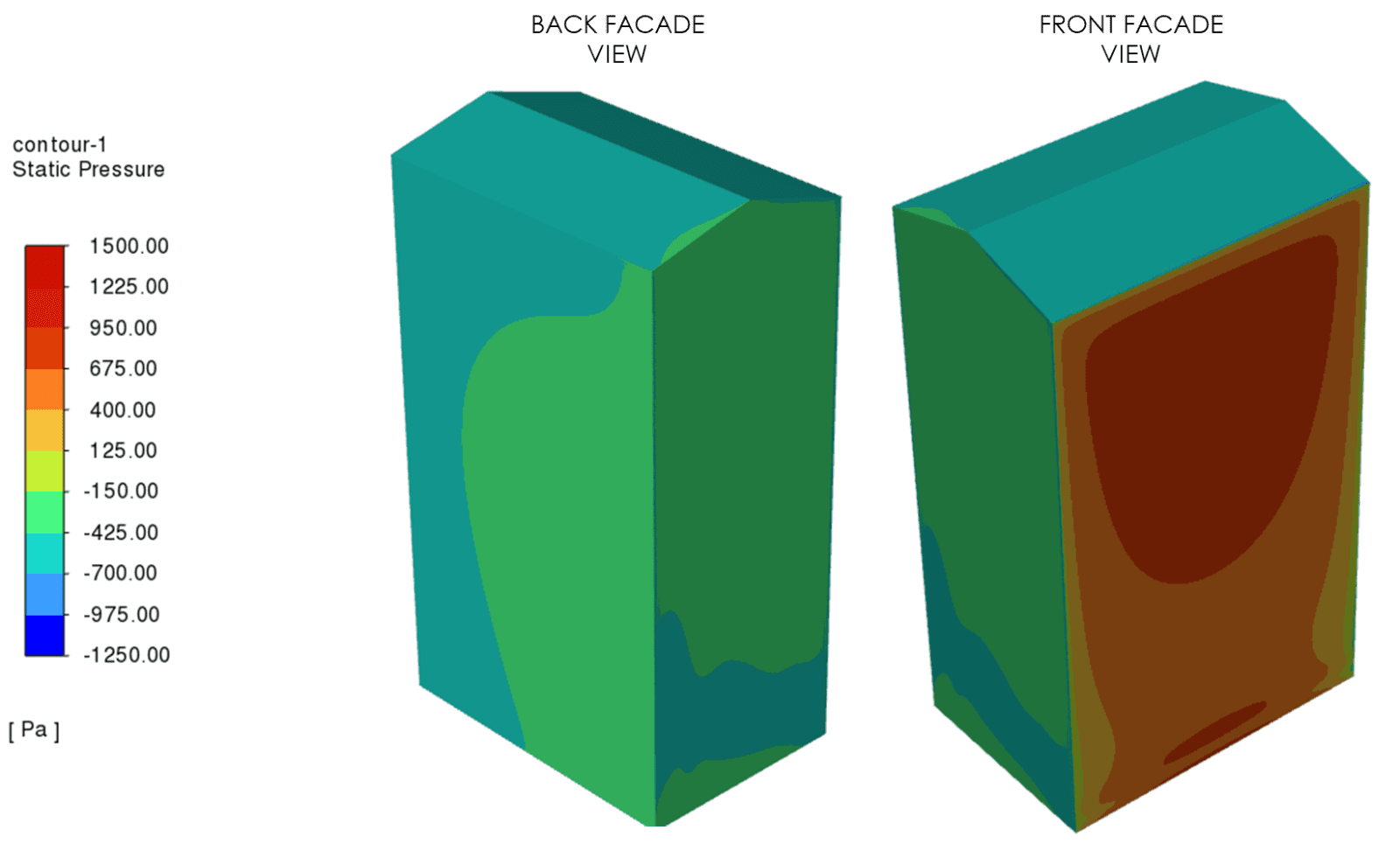
As a result of the CFD analyses, the pressure distributions formed on the surface of the building facade were visualized. According to Eurocode standards, loads were determined on the safe side based on average-minimum-maximum values at intervals of 0.25 Pa on the building facade surfaces.
The loads were plotted on the visual in kN/m² (kPa).
Wind Calculator automates the analytical wind load calculation according to EN 1991-1-4, providing a fast and reliable reference for tendering, preliminary design, and code-compliant initial sizing stages; indeed, for the 28.0 m/s input, zone-based loads and design outputs such as q = 1.409 kN/m² are clearly visible on the shared screens.
In contrast, when the same structure is solved in CFD with the same reference wind profile and similar boundary conditions, especially when the ABL, surrounding buildings, and detailed facade geometries are included in the model, the flow physics can be represented at a much higher resolution. As a result, the loads can be obtained in a more refined form, in many cases more realistically, and at levels that may reduce cost in some projects.
In summary, while the Eurocode approach provides a conservative design basis that remains on the safe side, CFD enables design optimization by offering a more physical and precise assessment under real environmental effects, including in complex geometries.
You can access the free Wind Calculator through the link below to calculate facade wind loads according to EN 1991-1-4 standards. You can also access the formulation codes related to the calculations.
https://alkazar.com.tr/windcalculator.html
To access the video of the CFD analysis run with the time-dependent Large Eddy Simulation turbulence model,