A neighboring building can significantly alter the wind flow around the main structure. However, this effect is not governed only by the distance between the two buildings. The way the neighboring building is oriented relative to the main structure can also play a decisive role in the distribution of façade and roof pressures.
To examine this effect, we considered two layout configurations. In the first case, the neighboring building is parallel to the main structure. In the second case, the building dimensions, wind input, and gap are kept unchanged, while the neighboring building is rotated by 45°.
In other words, the changing factor is not the building size or its distance from the main structure. It is only the orientation in plan.
So the question becomes:
When the neighboring building remains at the same gap but only its orientation changes, how do the façade and roof pressures on the main structure differ?
In our previous article, we evaluated the adjacent building effect defined in EN 1991-1-4 through the parallel neighboring building arrangement. In this article, we compare the façade and roof pressures that emerge in the CFD results when the orientation of the neighboring building changes.
Benchmark Setup
The comparison was carried out using a simple geometry. The main building was considered as a rectangular prism block with a flat roof. The neighboring building was modeled as an identical copy of the main building. This allowed the comparison to focus directly on the orientation of the neighboring building.
The main inputs used are as follows:
- Building width: 30 m
- Building depth: 20 m
- Building height: 25 m
- Reference wind speed: 28 m/s at 10 m height
- Terrain category: III
- Gap between the two buildings: 20.77 m
- Neighboring building arrangements: parallel arrangement and 45° rotated arrangement
In this setup, the climate input, building geometries, and gap were kept constant. The comparison focuses only on the orientation of the neighboring building.
Which Zones Were Used for the Comparison?
The CFD results were divided into zones consistent with the façade and roof zones used in EN 1991-1-4. This made it possible to interpret the continuous pressure distribution shown in the pressure contour images through familiar zones such as A, B, D, E, F, G, H, and I.
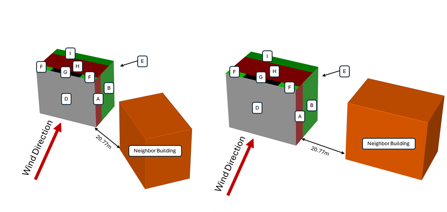
The purpose here is not to revisit the design-code calculation. The EN zones are used as a common reference language that makes the CFD results easier to read and compare.
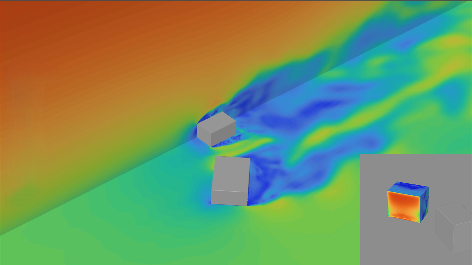
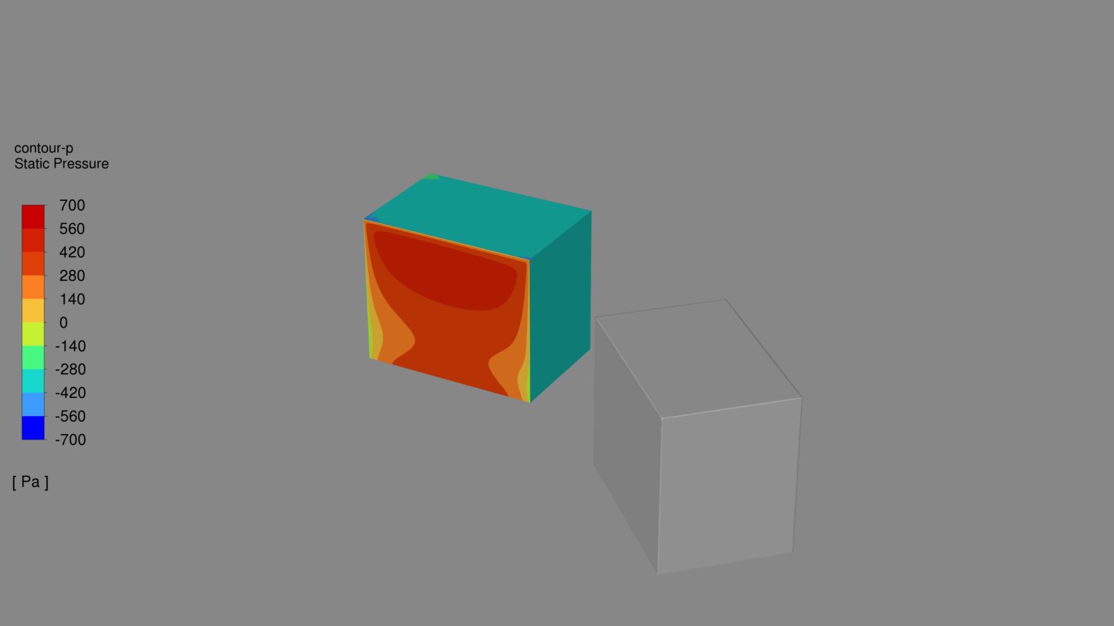
Flow Behavior in the Parallel Neighboring Building Configuration
The parallel arrangement makes the interaction between the two structures more pronounced. The space between the two masses forms a more defined passage zone. The flow is squeezed and accelerated in this region, and this effect becomes especially visible around edge, corner, and roof zones.
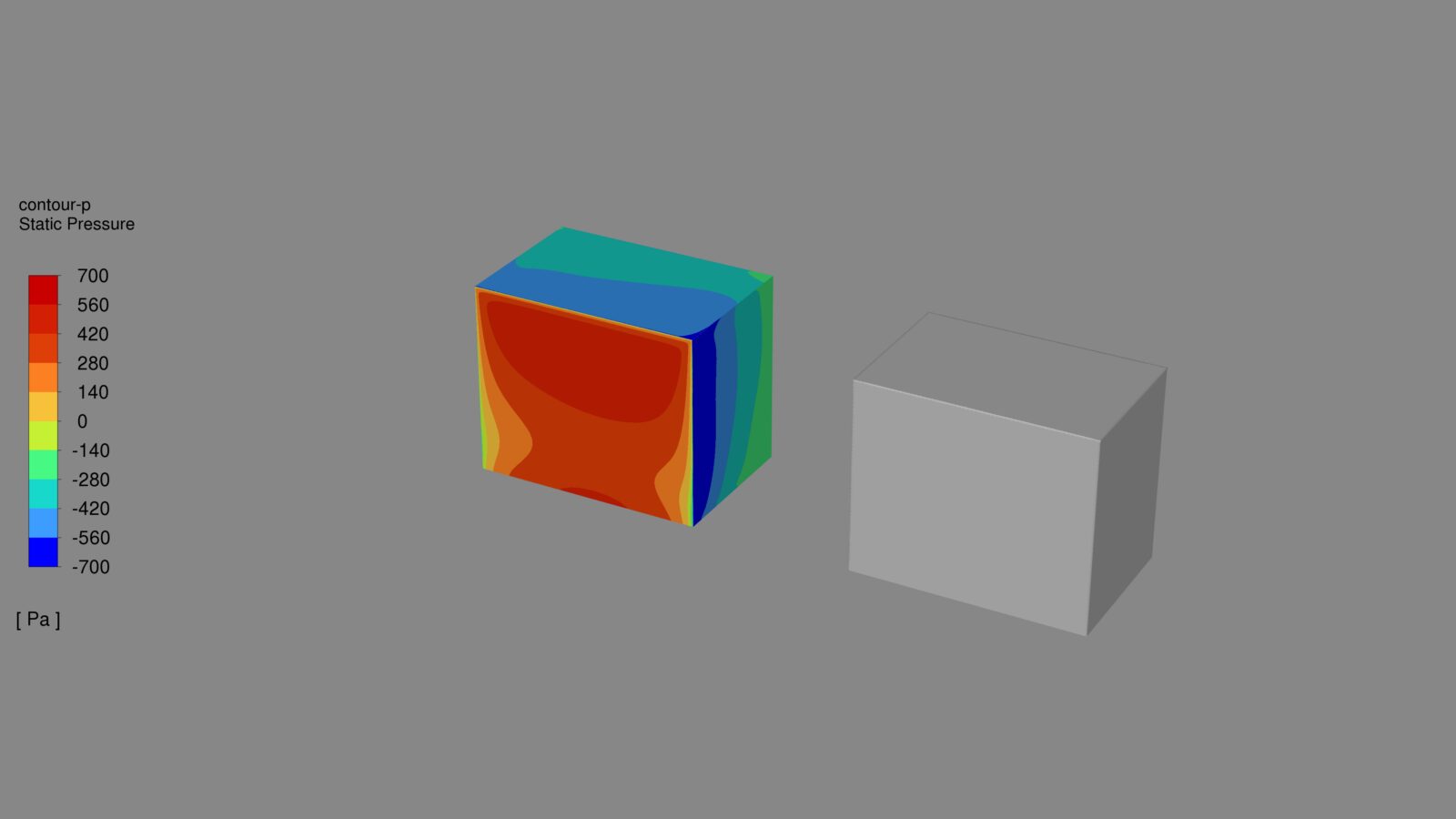
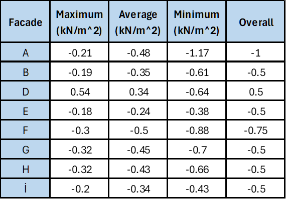
In this scenario, the positive pressure on the windward façade does not show a very large jump. In Zone D, the maximum pressure is approximately 0.54 kN/m², while the average value is around 0.34 kN/m².
The main difference appears on the suction side. In Zone A, the minimum pressure drops to approximately -1.17 kN/m², while values of approximately -0.88 kN/m² in Zone F, -0.70 kN/m² in Zone G, and -0.66 kN/m² in Zone H are observed.
This result shows that, in the parallel arrangement, the effect of the neighboring building should be read through local suction concentrations rather than a general increase in pressure.
What Changes When the Neighboring Building Is Rotated 45°?
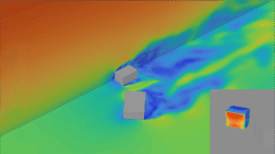
When the neighboring building is rotated 45° while the same gap is maintained, the way the flow interacts with the main building changes. In this case, the two masses do not create a passage zone as clearly defined as in the parallel scenario. The flow follows a more fragmented path, and the pressure field is distributed more broadly over the main building surfaces.

In the 45° scenario, the positive pressure on the windward façade remains at a relatively similar level. In the suction zones, a more limited and balanced behavior is observed compared to the parallel arrangement. This shows that the 45° arrangement does not eliminate the neighboring building effect, but that the effect is distributed more broadly across the surfaces.
Zone-Based Results Comparison
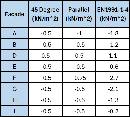
The figure and table below show the zone-based external pressure values for the same benchmark, comparing the 45° neighboring building arrangement, the parallel neighboring building arrangement, and the EN 1991-1-4 approach.
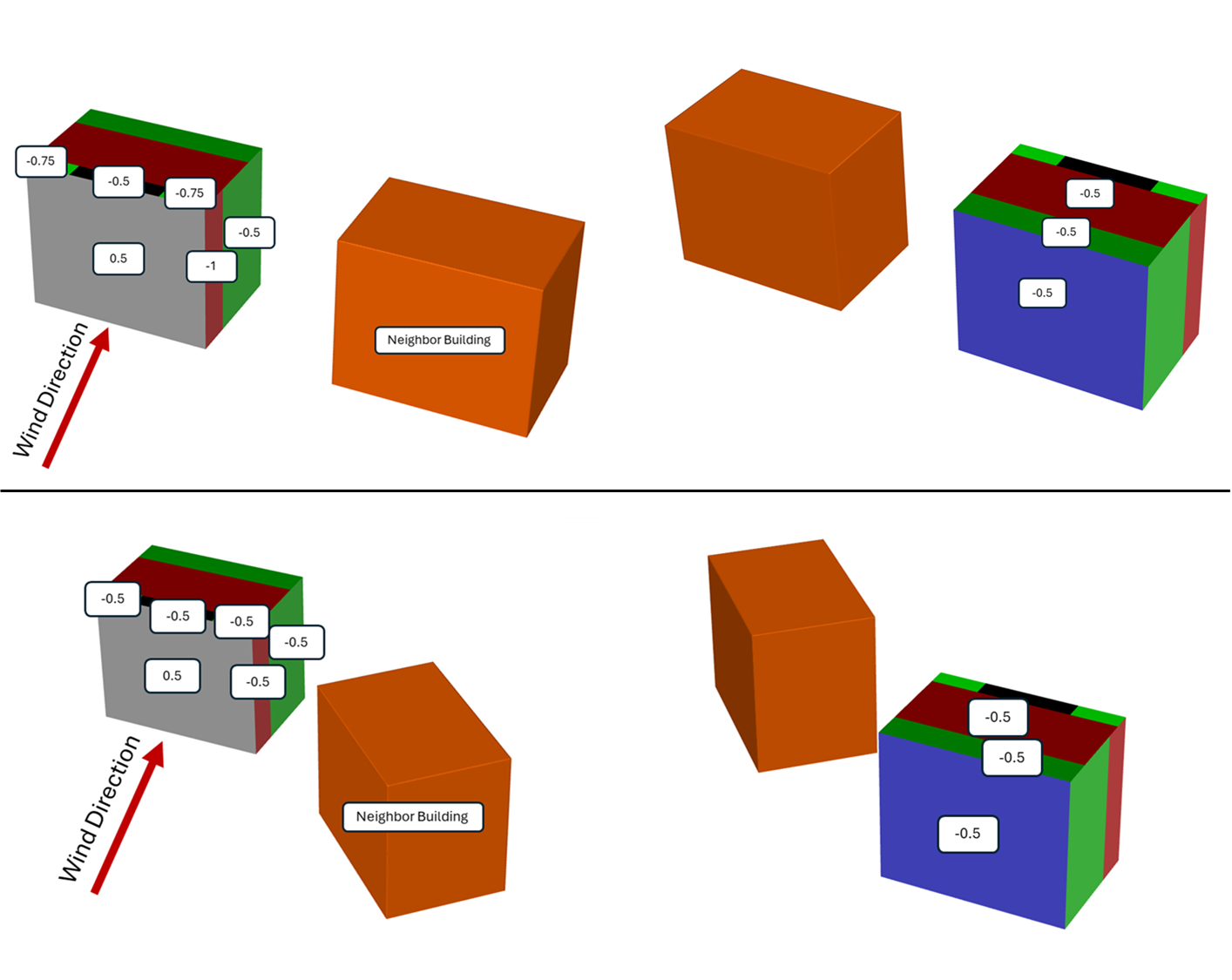
The purpose of the table is not to look only at individual values, but to show how the orientation of the neighboring building changes the regional pressure distribution while the same building and the same gap are maintained.
In this example, the two CFD scenarios produce similar results in some zones, while clear differences appear especially in the suction zones. In the parallel arrangement, the interaction between the two structures becomes more intense in certain edge and roof zones. In the 45° arrangement, the pressure distribution shows a more spread-out and balanced character.
The EN 1991-1-4 values were calculated using our publicly available Alkazar WindCalc tool. These values are included not to make a direct CFD-to-code comparison of the flow physics, but to show where the code-based design envelope stands. In this example, EN 1991-1-4 produces a more conservative set of pressure values. This is consistent with the role of EN 1991-1-4 as a generalized design framework rather than a method intended to resolve project-specific local flow distributions in detail.
The main message of the table is this: the same gap does not mean the same pressure distribution.
Why Does the Same Gap Not Produce the Same Result?
In both scenarios, the distance between the buildings is the same. Even so, the pressure distribution is not the same. This is because the gap alone is not enough to define the aerodynamic behavior. The position of the neighboring building relative to the wind direction, its angle in plan, and the flow relationship it forms with the main building must all be evaluated together.
In the parallel arrangement, the flow can be squeezed more distinctly between the two structures and can create stronger suction areas especially around edge and roof zones. In the 45° arrangement, the neighboring building affects the flow in a more fragmented way. Therefore, the pressure field is reflected onto the main building surfaces in a more distributed manner.
This difference is important for façade and roof design. In many cases, the design is governed not by the average pressure, but by local peak pressures. Cladding connections, parapets, roof edge elements, façade panels, and anchorage details are directly affected by this local behavior.
Conclusion
The clearest outcome of this comparison is this: even when the same building, the same wind climate, and the same gap are maintained, changing only the orientation of the neighboring building can change the pressure distribution on the façade and roof.
In the parallel arrangement, the suction zones become especially critical. More pronounced minimum pressures occur in sensitive zones such as A, F, G, and H. In the 45° arrangement, the pressure field shows a more distributed and balanced character.
This benchmark reminds us of a simple but important point: in urban aerodynamics, the same gap does not mean the same flow. The orientation of the neighboring building directly affects how the flow accelerates, where it separates, and how pressures are redistributed across façade and roof surfaces.