
Design to Deployment Enhancing Outdoor Air Conditioning Efficiency
One of the most crucial factors affecting performance is the ability of the externally positioned devices to supply as much fresh air at ambient temperatures as possible. The optimal placement of these air conditioning units outdoors must be carefully designed to prevent them from drawing in each other’s expelled air.
Air conditioners or central systems use outdoor air for cooling or heating functions. The atmospheric conditions for outdoor units are crucial for the energy consumption performance during operation. For instance, during the summer (cooling period), if they must operate by processing air that is even hotter than the normal outdoor temperature, electricity consumption will increase. This is because the air conditioner might have to operate continuously at maximum capacity instead of intermittently at lower speeds to maintain the required set temperature.
A critical issue affecting this situation is the ability of the outdoor unit to intake atmospheric air without pressure losses and/or to continue its process by drawing in only the outside atmospheric air as much as possible. If it begins to draw in the air expelled by another nearby unit, it may have to operate continuously at the highest capacity after a certain point. This would maximize energy consumption. Additionally, if we also consider the increase in temperature on the body of the outdoor unit, which is not shaded and exposed to prolonged sunlight, the criticality of the situation increases.
In this blog post, we simulated the situation using a simple model through computational fluid dynamics (CFD), thereby examining cost-effective and time-saving conditions. The computational fluid dynamics method is the most advantageous method for:
- Determining how much bypass air is created by the climate control devices in the outdoor environment,
- Observing how the exhaust temperatures of the air conditioners increase over time relative to the temperature they absorb,
- Planning how elements around the device that will affect the flow should be positioned for visualization and in-depth optimization. This allows for identifying potential issues early in the design process and developing appropriate solutions.
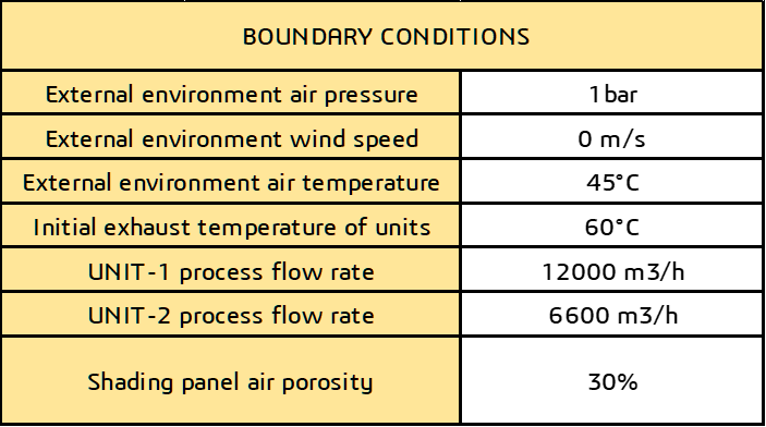
For the specified conditions, the analysis examined how a shading cloth laid on the roof, preventing the devices from heating through radiation from the sun, affected system performance. In a weather condition with 0 m/s wind and an outdoor temperature of 45°C (taking Dubai as a reference), it is expected that 7 air conditioning units will intake fresh air from open areas.
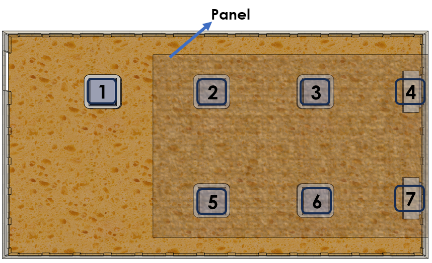
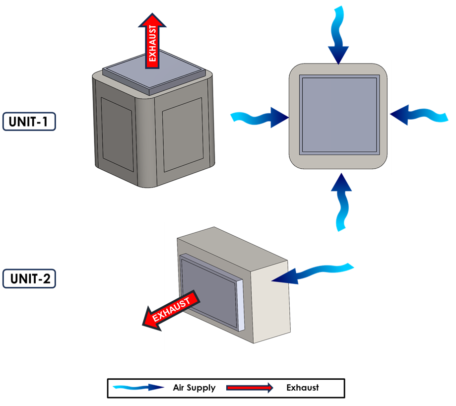
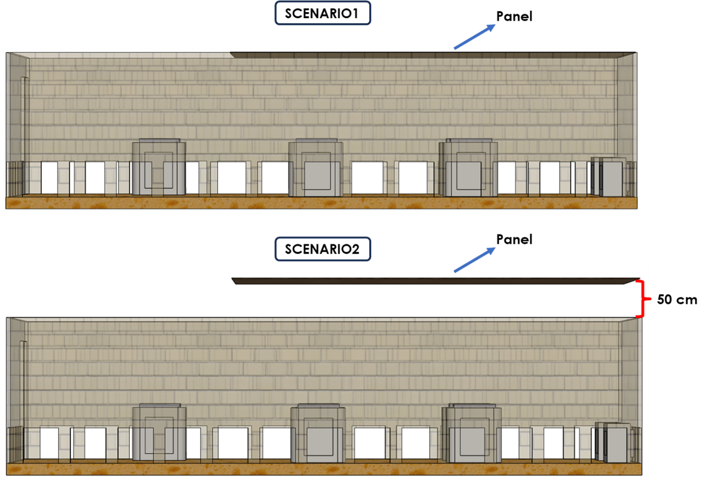
The positions for the exhaust and intake of two types of devices were defined as shown in the visual. To simulate this situation, an analysis of an outdoor air conditioning unit involving two different scenarios was conducted. A comparison of the performance of the air conditioning devices between these configurations was made.
In these time-dependent analyses, two scenarios were considered:
- Scenario1: The panel is in contact with the ceiling
- Scenario2: The panel is raised 50 cm above
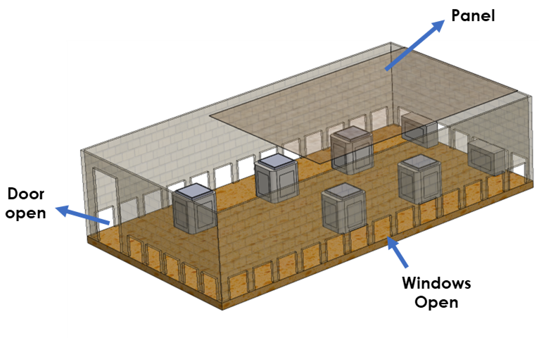
The structure was modeled with walls surrounding it, but included openings and an open door to allow air intake from small gaps. Additionally, space was left at the edges of the fabric to ensure it could also intake fresh air from above.
Additionally, it is known that the units exhaust air at 60°C when the outdoor temperature is 45°C (dT=15°C).
- Scenario 1, the indoor temperature has increased due to the shading panel partially blocking the exhausted air.
- Since the devices constantly emit air that is 15°C hotter than the air they intake, the return suction temperatures have also increased.
- In Scenario 2, when the panel is raised by 50 cm, the exhausted air is allowed to be discharged without affecting the environment, resulting in lower suction temperatures for the devices.
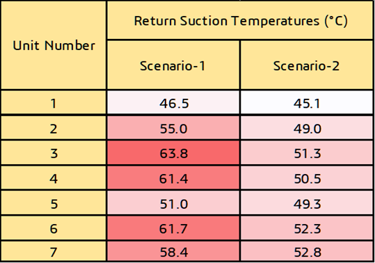
Scenario 2 is more advantageous than Scenario 1 in terms of system performance and will consume less energy.


