Datacenters Thermal Performance Analyses
Since 2010, the number of internet users worldwide has doubled, while global internet traffic has increased 12 times or 30 percent per year. With the increasing demand for data and digital services global internet traffic is expected to double by 2022, to 4.2 zettabytes (4.2 trillion gigabytes). Most of the IP traffic goes through data centers. Therefore, data centers and therefore the use of electrical energy are increasing. According to the Data Centers and Data Transmission Networks report published by the International Energy Agency in 2019, the power consumption of data centers on a global scale in 2019 is approximately 200 terawatt-hours. This is approximately 0.8 percent of the total electrical energy consumed in the world.
The biggest power demand in data centers is due to cooling loads. This ratio corresponds to approximately more than half of the energy consumed in data centers. Considering all these, the most efficient and least lossy designs will be the most reasonable solution approach for data centers.
For this reason, air flows should be examined in order to reduce the energy consumption of cooling systems at the point of sustainability in datacenters. Before applying what is planned in theory, the air flow inside should be examined in a way to answer the question whether it will actually be as planned in theory. The main problems encountered in airflow management can be:
- Hot air recirculation
- Cold air bypass
- Leakages
- Over-provisioned and under-provisioned air supply
- Airflow and temperature non-uniformity
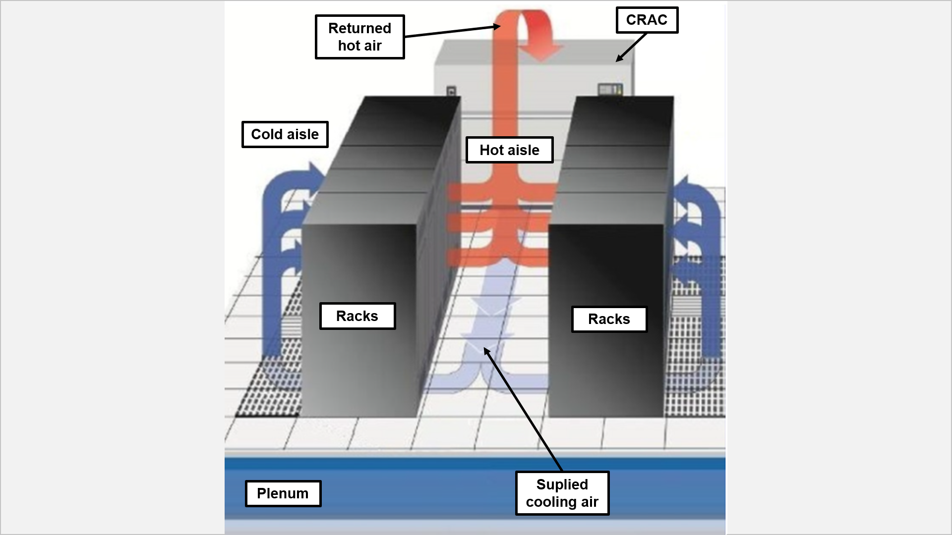
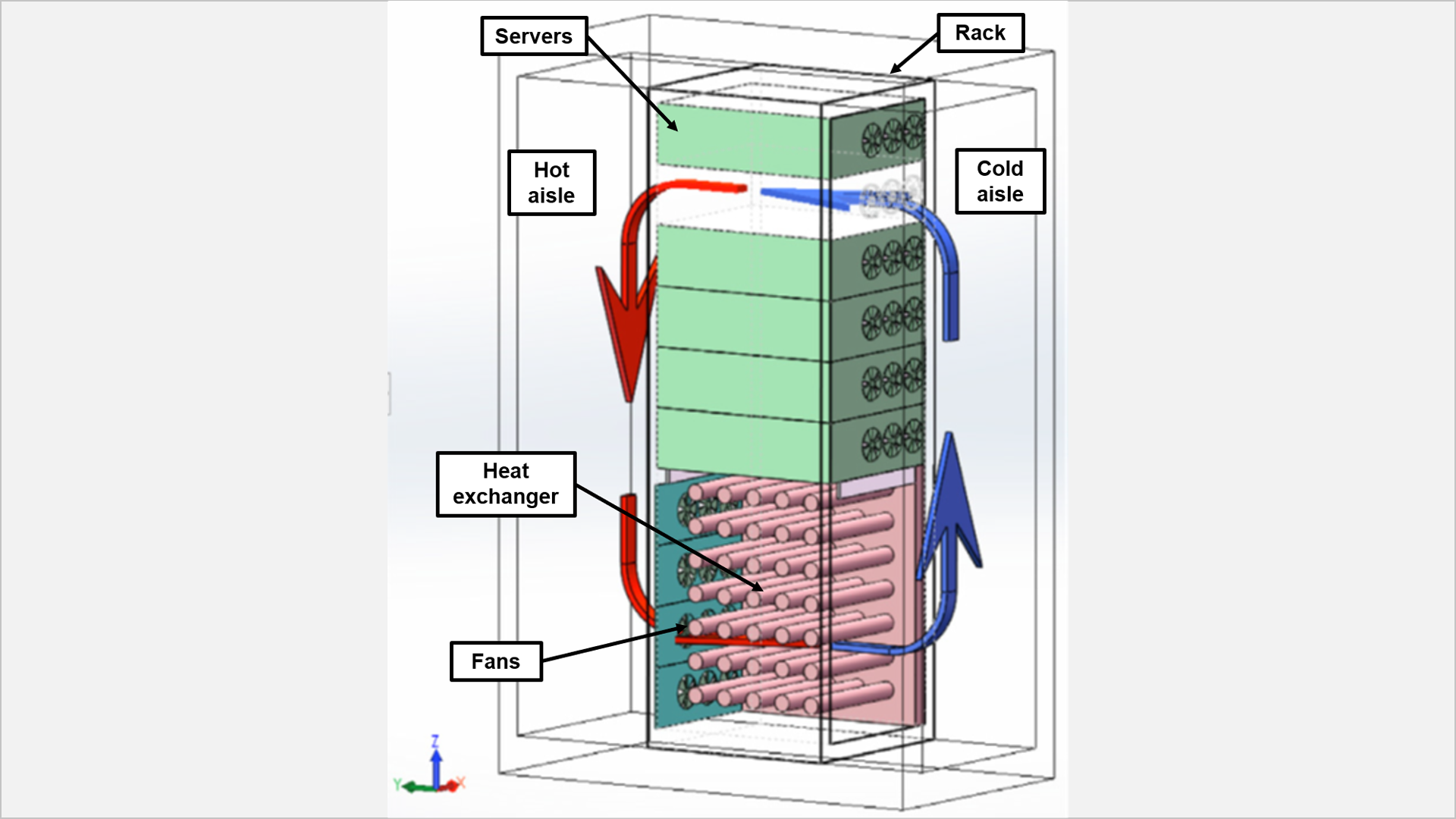
Two types of cooling systems are generally used in datacenters. These; are long distance and short distance cooling systems. Sample schematic of long distance cooling systems are given in Figure 1 and short distance cooling systems in Figure 2.
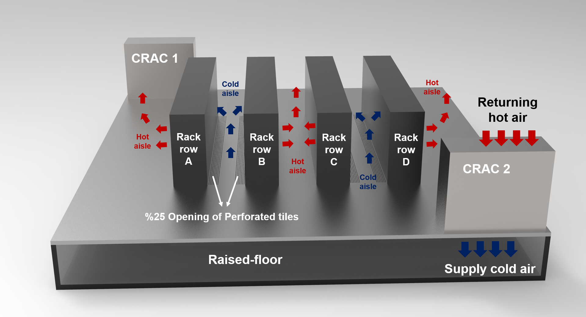
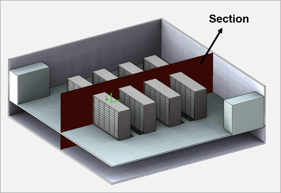
In this post, a sample case analysis study for datacenters is made. The datacenter room and layout used in the case analysis are shown in Figure 3.
There are many parameters to examine in airflow management in datacenters. These; aisle containment, leakages, position of air conditioners, air permeability of grid, etc.
Two parameters were considered in the case analysis studies for the datacenter room. These are the height of the raised floor and the ceiling height of the room.
In other saying, a new datacenter room will be built. The cooling design criteria of this room, the position of the air conditioners, the air permeability rates of the grids have been determined, but the height of the raised floor and the ceiling of the room that can provide the best cooling performance for this room is unknown.
In the case analysis study, raised floor and ceiling heights showing the best performance in terms of cooling for datacenters were determined. For this, the height of the raised floor was primarily determined. In this context, 5 scenarios with 5 different heights were created. The best performing height from these scenarios was used to determine the ceiling height of the room. The best performing raised floor height and 8 different ceiling heights are planned. These scenarios examined in case analysis studies and their contents are explained in the visual in Figure 4.
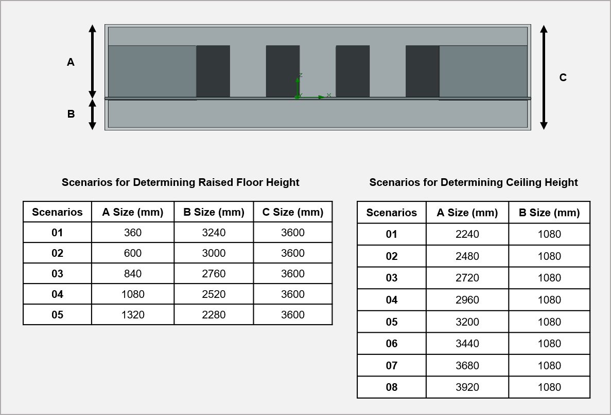
As can be understood from Figure 4, in the scenarios created to determine the height of the raised floor, the height of the room is fixed as 3.6m. That is, as the floor height increases, the space between the upper part of the rack cabinets and the ceiling will narrow. 5 scenarios were created by increasing the raised floor heights in 240 mm intervals. In the scenarios created to determine the ceiling height, the raised floor height is 1080 mm and fixed, 8 scenarios were created by increasing the ceiling height in 240 mm intervals.
As can be seen in Figure 3, long distance cooling system was preferred in case analysis studies. For the cooling of the datacenter, two air conditioners, each with a cooling load of 100 kW, a blowing rate of 8.36 m3/s and a blowing temperature of 18 °C, were used. These devices blow cold air into the vent parallel to the floor and suction from the aperture parallel to the ceiling. The inside of the raised floor is modeled as completely empty. Of course, in real analyses, approximate pressure loss curves are created in this volume depending on the density of the cable and other apparatus. Room components such as cable lines that may be found in raised floors and leaks in the room have been ignored.
There are 4 rows of rack cabinets in the room. There are 10 cabinets in each row. According to the naming in Figure 3, each rack cabinet in rows A and C has a heat load of 5 kW, and those in rows B and D have 3 kW. There is a grid on the ground in front of each cabinet. There are a total of 40 grids in the room. These grids are 25% air permeable.
The datacenter room was built with the idea of hot and cold aisle. No containment has been modeling in the aisle. The height of the rack cabinets and air conditioning devices is 2m.
The scenarios created were analyzed using the CFD (Computational Fluid Dynamics) method under these conditions. The results of the analyzes made for the raised floor height are given in Figure 6 and the results of the analyzes made for the ceiling height are given in Figure 7.
Analysis results were evaluated according to ASHRAE standards. As shown in Figure 5, temperature distributions are examined in a vertical section taken from the middle of the rack cabinets. In the performance evaluation, the inlet temperature of the air in the aisle designed as cold into the rack cabinets was used. The temperature of the air inletting the rack cabinets should be maximum 27 °C according to ASHRAE standards.
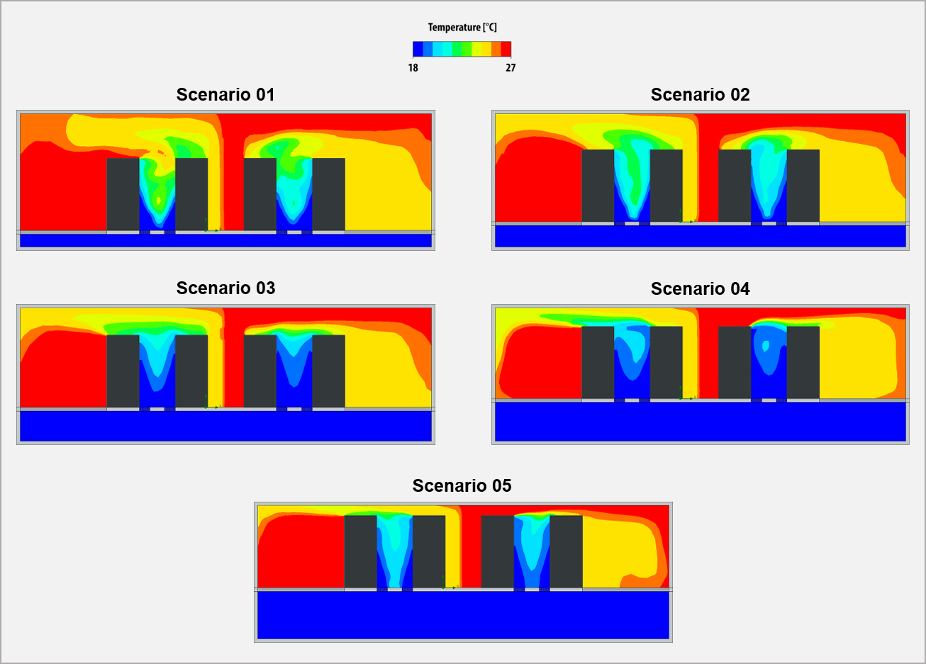
Scenario 04 (1080 mm) has been determined as the scenario providing the best performance from raised floor heights. The effective parameter here is the homogeneity of the air passing through the 25% permeable grids. As the ground height increased, the area under the floor maintained the pressure difference in the direction of flow stream and a smoother air flow from the grids was provided. However, due to the fixed height of the room, as the floor height increases, the distance between the upper part of the rack cabinets and the ceiling has narrowed. As this distance decreases, the effect of ceiling height is activated. The reduction of the space between the top of the rack and the ceiling restricts the free movement of the hot air in the room. Thus, it causes intense mixing of cold-hot air currents and an increase in temperatures. Of course, this situation can be eliminated with different architectural approaches (suspended ceilings, different closures, etc.), but the aim is to examine the system with one variable.
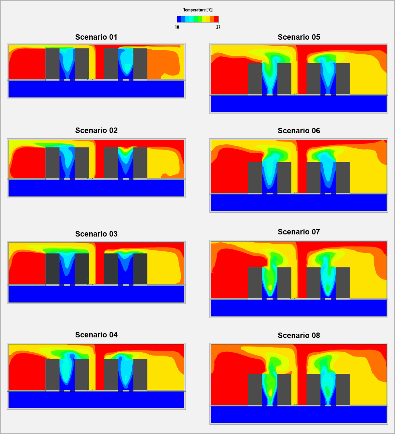
Scenario 03 (2720 mm) is determined as the scenario providing the best performance from ceiling heights. As the ceiling height increased, the cooling performance in the aisles increased and the best was observed in scenario 03. However, after this scenario, as the ceiling height increased, the cooling performance in the aisles started to decrease and then reached a constant distribution and did not change much. Related to this, the increase in hot air circulation has been effective.
As a result of the case studies conducted for the data center, the best performing raised floor height and ceiling height were determined. With these heights and the accepted conditions, the air distribution in the room was optimized and their effects on thermal performance were examined. Thus, the importance of criticizing each design at the first stage arises, albeit with a simple approach. See you in our next post where we examine datacenters with different variables.
References
- A review on airflow management in data centers (Wen-Xiao Chu, Chi-Chuan Wang)
- A Comparison of Parametric and Multivariable Optimization Techniques in a Raised-Floor Data Center (Srinarayana Nagarathinam, Babak Fakhim, Masud Behnia, Steve Armfield)
- Optimization of Data Center Room Layout to Minimize Rack Inlet Air Temperature (Siddharth Bhopte, Dereje Agonafer, Roger Schmidt, Bahgat Sammakia)
- Comprehensive study on the effects of plenum depths on air flow and thermal managements in data centers (S.A. Nada, M.A. Said)
- Airflow and Cooling in a Data Center (Suhas V. Patankar)
- Comparison Between Numerical and Experimental Results of Airflow Distribution in Diffuser Based Data Center (Qifei Jian, Qiaoli Wang, Haoting Wang, Zheng Zuo)
- Airflow distribution through perforated tiles in raised-floor data centers (Kailash C. Karki, Suhas V. Patankar)


